

High Voltage Capacitor Compensation Cabinet
Jul 11, 2023
High voltage capacitor compensation cabinet
The function of the capacitance compensation cabinet is to balance the inductive load of the equipment, improve the power factor, and improve the utilization rate of the equipment.
In order to improve the energy waste caused by low power factor in the power grid and the unfavorable factors of capacitor compensation cabinet production, it is necessary to effectively improve the power factor of the power grid.
But obviously, it is unreasonable and usually impossible for these reactive power to be provided by generators and transmitted over long distances. A reasonable approach is to generate reactive power where it is needed, that is, to add reactive power compensation equipment and devices. That is, the capacitance compensation cabinet.
The majority of load types in the power system belong to inductive loads, coupled with the widespread use of power electronic equipment by power companies, resulting in a lower power factor in the power grid. A lower power factor reduces equipment utilization, increases power supply investment, damages voltage quality, reduces equipment service life, and greatly increases line losses. Therefore, by connecting capacitor compensation cabinets in the power system, inductive loads can be balanced, power factor can be improved, and equipment utilization can be improved.
Generally speaking, low-voltage capacitance compensation cabinet is composed of cabinet body, busbar, fuse, disconnector fuse bank, capacitor contactor, lightning arrester, capacitor, reactor, primary and secondary conductors, terminal strip, power factor automatic compensation control device, panel instrument, etc.
Its basic principle: In actual power systems, most loads are asynchronous motors. Its equivalent circuit can be seen as a series circuit of resistors and inductors, with a large phase difference between voltage and current and a low power factor. After parallel connection of capacitors, the current of the capacitors will offset a portion of the inductance current, thereby reducing the inductance current and the total current, resulting in a smaller phase difference between voltage and current, and an increase in power factor.
Function of compensation cabinet: The current leads the voltage by 90 degrees, and the parallel connection of capacitors is used to increase the line voltage and reduce reactive power loss.
Attention for opening the capacitor cabinet: Before opening, check whether all switches and circuit breakers are closed, then close the cabinet door and turn the door handle to the closed position. Confirm that there is no error, and then close the knife switch.
In order to improve the energy waste caused by low power factor in the power grid and the unfavorable factors of capacitor compensation cabinet production, it is necessary to effectively improve the power factor of the power grid. Obviously, it is unreasonable and usually impossible for these reactive power to be provided by generators and transmitted over long distances. A reasonable approach is to generate reactive power where it is needed, that is, to add reactive power compensation equipment and devices.
The capacitance compensation cabinet is mainly used to optimize the quality of power supply. Because there are many inductive loads in our real life, the COS value of the power grid will be smaller, and the active power of the electric energy with a Nameplate capacity will be less, and the reactive power will be increased, leading to the waste of electric energy; Thus, we artificially add appropriate capacitive loads to increase the COS value, resulting in an increase in active energy. When the COS value is equal to 1, it is the impedance load with the highest utilization rate, but this is an ideal state.
In the power system, electric motors and other coil devices are widely used. This type of device needs to consume a portion of the inductance current that is not doing work from the circuit in order to obtain a portion of the current from the circuit to do work. This causes an additional increase in the current on the circuit. 10Kv capacitor compensation is used to compensate for inductance current, increase power factor, and reduce reactive current.
The capacitance compensation cabinet is a reactive power on-site compensation device designed for energy conservation and consumption reduction of motors. It is connected in series in the motor rotor circuit. By changing the phase relationship between the rotor current and rotor voltage, the phase relationship between the motor stator current and voltage is changed, achieving the goal of improving the power factor and overload capacity of the motor itself, reducing the motor stator current, and reducing the motor's own losses.
The function of reactive compensation cabinet is to make reactive compensation. With the help of reactive compensation equipment, it can provide necessary reactive power, improve the power factor of the power grid and electrical equipment in the power supply system, reduce the loss of power supply transformers and transmission lines, improve the power supply efficiency of the power grid, improve the power supply environment, and improve the quality of the power grid.
The reactive power compensation cabinet plays an important role in power supply. If there is a reasonable compensation device, it can achieve the maximum reduction of power grid losses. On the contrary, improper selection or use may cause various factors such as power supply system, voltage fluctuations, and increased harmonics.
Reactive power compensation is the use of an external current source to compensate for the reactive power consumed during load operation. The equipment that provides this current source becomes a reactive power compensation device, and a common compensation device is a parallel power capacitor.
Safety operation specifications for reactive power compensation cabinets
1. Before opening the reactive power compensation cabinet, the circuit breaker or isolation switch must be disconnected to allow the discharge device of the reactive power compensation cabinet to automatically discharge. The cabinet door can only be opened after three minutes, and manual discharge is required after opening the cabinet door.
2. The special sound emitted by reactive power compensation during operation is a precursor to internal insulation collapse, and the operation should be immediately stopped to find the faulty high-voltage capacitor compensation.
3. The expansion of the reactive power compensation shell is caused by overvoltage, which leads to the decomposition of the medium and the precipitation of gas. It is necessary to immediately stop operation to search for faults in high-voltage capacitor compensation.
4. It is prohibited to switch on immediately after disconnection, as this will cause serious damage to other electrical equipment and capacitor compensation itself. Generally, a time interval of more than three minutes is required. For automatic switching of reactive power compensation cabinets, if the power factor of the grid changes rapidly, the delay time should be appropriately extended.
5. Good ventilation is required inside and outside the reactive power compensation cabinet to extend the service life of the capacitor.
6. Keep the surface of the reactive power compensation cabinet clean to avoid flashover accidents
PRODUCT LINK
http://www.switchgear-china.com/switchgear/high-voltage-switchgear/33kv-power-switchgear.html
PRODUCT PHOTO


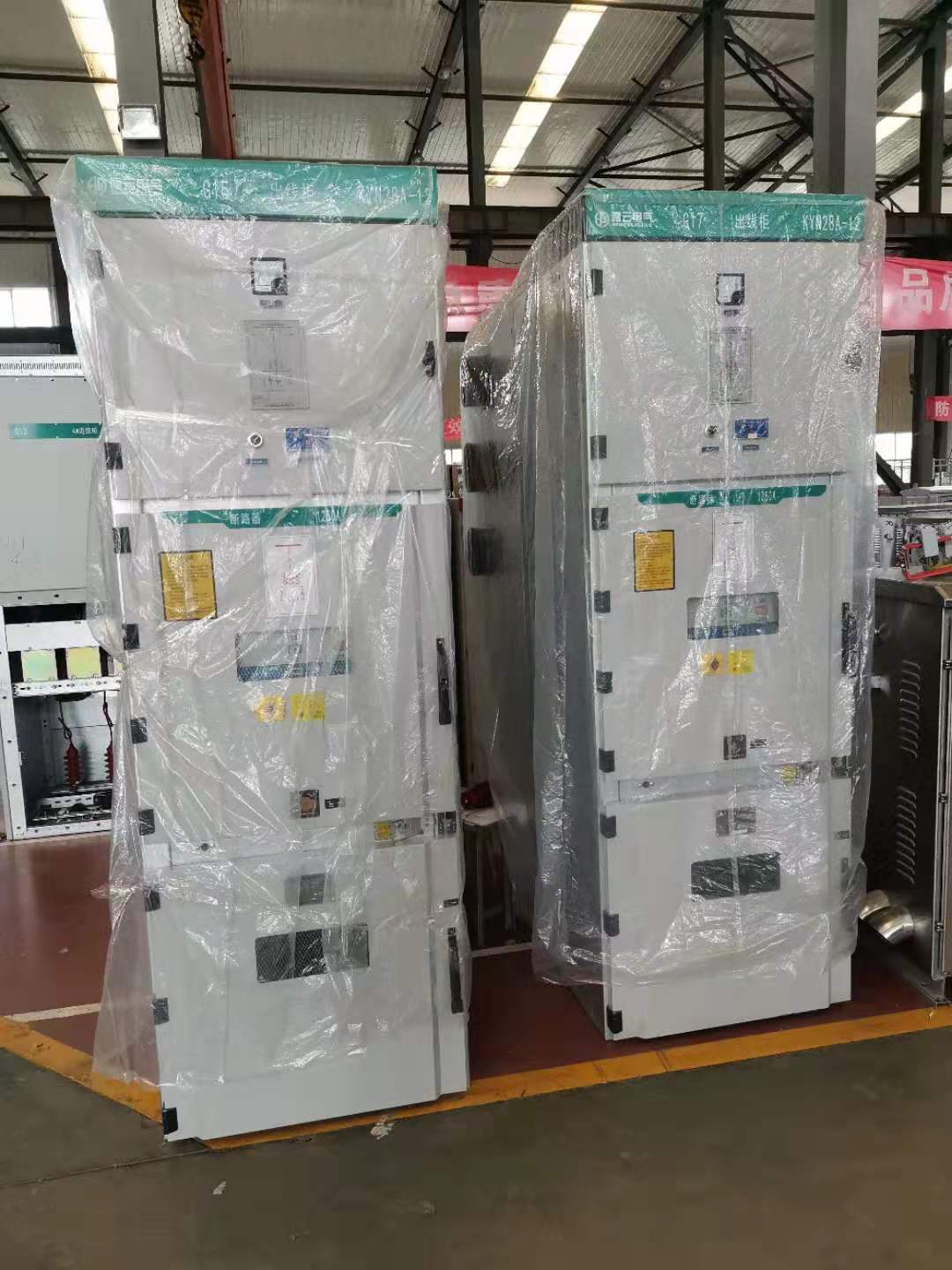

This product is usually customized.
We are a manufacturer and have a professional technical department that can design and provide solutions according to customer needs.
Please contact our sales personnel to obtain design drawings
Here are our customer examples for your reference
US Clients
| 7.1 | Technical guarantee schedule : ring main units | ||||
| Item | Description | Unit | Requirement | Guaranteed value | |
| 1.0 | Type /model | - | State | RMU | |
| 2.0 | Insulating medium | - | Vacuum /SF6 | SF6 | |
| 2.1 | Interrupting medium | Vacuum /SF6 | SF6 | ||
| 2.2 | Transformer protection (Fuse/circuit breaker) | circuit breaker | circuit breaker | ||
| 3.0 | Application standard | - | IEC and BS | IEC | |
| 4.1 | Nominal Voltage rating | kV | 11 | 11 | |
| 4.2 | Maximum Voltage rating | kV | 12 | 12 | |
| 4.3 | Rated Frequency | Hz | 50 | 50 | |
| 4.4 | Power Frequency withsand voltage | kV | 28 | 28 | |
| 4.5 | Impulse withstand voltage | KVp | 95 | 95 | |
| 5.0 | Rated current busbars | A | 630 | 630 | |
| 5.1 | Rated Current cable (switch) | A | 630 | 630 | |
| 5.2 | Rated current (T-OFF) | A | 125 | 125 | |
| 5.3 | Rated current for circuit breaker | A | 125 | 125 | |
| 6.0 | Breaking Capacity | ||||
| 6.1 | Closed loop (Cable switch) | A | 630 | 630 | |
| 6.4 | Short circuit breaking current | kA | 20 | 20 | |
| 6.5 | Rated making capacity | kA | 50 | 50 | |
| 6.6 | Rated Short time current 3 sec | kA | 20 | 20 | |
| 7.0 | Dimensions | CTC | CCTC | ||
| Height | mm | 1950 | 1950 | ||
| Width | mm | 1170 | 1545 | ||
| Depth | mm | 750 | 750 | ||
| 8 | Are RMU's manufactured under license, if so state name of the company | HENAN FENGYUAN POWER TECHNOLOGY CO.,LTD. | |||
IF NEED MORE DETAILES,PLEASE FEEL FREE YO CONTACT US


