High and low voltage switchgear installation method steps
Aug 25, 2020
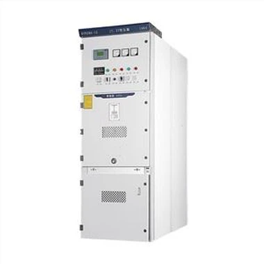
First look at the inspection. Regarding the unpacked switchgear, carefully check the quantity and standard according to the planning drawing and the imitation list to see if it meets the requirements, whether the high-voltage switchgear shell is damaged or rusted, and check whether the accessory spare parts are complete . After unpacking, check the factory certificate, imitation bill, internal wiring diagram and other technical data documents. After the high-voltage power distribution cabinet is unpacked, the power distribution cabinets are numbered according to the planning drawings, and they are sequentially moved into the equipment positions in the substation.
After the switchgear is installed on the channel steel, use a thin shim to roughly adjust the level of the high-voltage cabinet, and then adjust the other one based on the other one, so that all the high-voltage cabinet panels are common and the gap is even. After the bolts are fixed, keep 2 to 3 gaps between the cabinets, and finally fix the cabinets to the base channel steel permanently with fixing bolts or welding. In order to be beautiful, the welding seam should be welded on the inside of the cabinet, and no less than 4 places, each of which is 80 to 100.
Connect the bus. The main bus bar and appearance on the switchgear are provided by the switch factory, and can also be manufactured at the construction site according to the planned drawings. The connection of the main bus bar, the connection between the main bus bar and the lower bus bar, and the connection between the bus bar and the exterior are connected by bolts. The connection surface of the bus bar should be coated with electric compound grease. The tightening degree of the bolts and the connection of the connection surface shall be determined by the torque wrench according to the rules. Tighten the bolt to control the torque value.
Handcart type high voltage switch cabinet equipment. The equipment method is basically the same as the fixed high-voltage switchgear, the difference is to ensure the interchangeability of handcarts. Each handcart-style moving contact must be adjusted together, that is, the moving and static contact bases must be adjusted together and touched tightly to ensure interchangeability. Check the plugs and auxiliary contacts of the secondary circuit of the high-voltage power distribution cabinet, and the welding is firm. The electrical or mechanical locking device is accurate, so that the handcart cannot be pulled out in the closing position. The safety partition can be opened and closed flexibly and can move with the in and out of the handcart. The touch between the grounding equipment of the handcart and the fixed structure of the high-voltage power distribution cabinet should be excellent. The control cables in the high and low voltage switchgear are firmly fixed and will not affect the movement of the handcart.
The laying of electrical equipment, appliances, and non-live metal parts of the protective grounding branch line should comply with the following rules: tightly connected and strong, the cross-section of the protective grounding wire is selected accurately, and the parts that need corrosion protection are evenly painted without loss. The road runs fair, the color code is accurate, and the equipment and buildings are not polluted after painting. Check the "5-proof" chain of the power distribution cabinet, the function is completely reliable.
The approximate process is:
The equipment orientation of the electrical components is in line with the planning drawings, and the equipment is robust and reliable;
1. The sectional area of a line meets the drawing request;
2. The copper busbars of the primary line are tin-plated, and the touch area meets the requirements;
3. The screws for the one-time connection are fastened and reliable, and the touch resistance meets the requirements;
4. Phase sequence placement: viewed from the front, from left to right, from top to bottom, and from far to near as A, B, C;
5. The electrical gap is greater than -10mm, and the creepage distance is greater than 25mm;
6. The ground row and zero row should be equipment according to the drawings;
7. All kinds of micro notes are complete and good;
8. The switch opening and closing operation is flexible and reliable without obstruction;
9. The wiring of the secondary line is consistent with the planning drawing, and the power-on attempt is correct;
10. Power frequency withstand voltage: 2kV/min, no flashover, no breakdown.