Burnout Fault and Countermeasures of MNS Low Voltage Drawer Switch Cabinet
May 09, 2023
Burnout Fault and Countermeasures of MNS Low Voltage Drawer Switch Cabinet
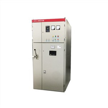
MNS low-voltage drawer type switchgear is favored by many power engineering customers for its advantages such as convenient maintenance, multiple group outgoing circuits, and small footprint. Although there are many manufacturers in the field, there are varying levels of technical expertise and production volume. Many small and medium-sized switch factories, due to their weak technical foundation, do not have a grasp of the specifications and standards related to the machinery and equipment in the distribution room. There are risks in the design and installation of drawer cabinets and switch cabinets, coupled with poor customer operation and maintenance management, and the aging of components in the cabinets due to increased operating time, This will lead to a high incidence of high-voltage switchgear accidents and even major accidents such as burning damage.
1. Common faults experienced
On the morning of July 28, 2019, an MNS low-voltage drawer cabinet that was operating normally in a certain distribution room suddenly ignited and caught fire. In order to avoid the expansion of common faults, the on-site operation and maintenance management staff sucked the upper level 35kV power switch and carried out firefighting. However, the firefighting immediately did not cause the large-scale model to catch fire. It was determined that the open fire was the D28 feeder cabinet on the bottom pressure side, which was severely burned and had lost its operational function. The adjacent cabinets were not affected, and after extinguishing the fire, the key load funds were invested in the reserved route, and the funds were put into operation again.
After confirming with the on-site staff, the distribution room was fully funded and put into operation in 2005, and it operated normally during the period without any maintenance records. Before the emergence of the fire alarm system, there were no common faults, power trips, power outages, or large-scale startup or shutdown of machine equipment (equipment) in the outgoing power switches and loads of each group. At the same time, after checking the operation records, it was determined that the three-phase five wire switch current meters of each module were normal and there was no load condition.
2. Analysis of common faults
2.1 Common faults on site
As shown in Figure 1, the D28 cabinet is damaged, and the electronic components in the cabinet are in a coke like shape. The metal material shell frame has been deformed, and the components and markings are severely damaged and cannot be distinguished. After checking and analyzing some of the burn marks on the spot, as shown in Figure 2, the metal material shell frame of the outlet module (bottom one) of the eighth circuit group was more severely burned, and the level of burn damage gradually decreased from bottom to top.
2.2 Common root causes of faults
Based on a detailed investigation and sampling of the on-site conditions of the D28 cabinet, as well as inspection and comprehensive analysis of the samples, simulation was applied to restore the operating conditions. The conclusion was drawn that the key reason for the ignition of the high-voltage switchgear was the single-phase grounding short circuit fault of the three-phase five wire terminal conductor of the eighth circuit power switch, which caused electro-optic charging and discharging and ignition. In depth analysis: After inspecting the connectors on both sides of the inlet and outlet of the eighth circuit of the D28 cabinet, there were no obvious burn marks on the connectors. At the same time, the condition of the internal isolation switch was checked, and there were no abnormalities in the internal conductors. The internal short circuit fault condition of the connectors and isolation switch can be cleaned. After inspecting the burned sample of the eighth circuit of the D28 cabinet, it was found that the three-phase five wire terminal B phase copper transmission line of the eighth circuit power switch was multi-stranded 70mm ² And it has melted off, and there is also a large-scale burning and melting situation at different levels in the AC phase.
The eighth circuit power switch three-phase five wire terminal B phase copper transmission line is a copper braided wire with a melting point temperature of 1083 ℃. Other key flammable substances in the cabinet are PVC plastic, with an ignition temperature of 350 ℃. Referring to the temperature time characteristic curve of fire accidents in the ISO834 national standard, the high temperature after ignition for 2 hours is about 950 ℃, which is lower than the melting point temperature of the conductor. Moreover, the accurate measurement line of the voltage transformer on the outlet side of the power switch group is 4mm ² But it hasn't melted yet. Based on the above analysis and inference, the cause of conductor melting is not caused by continuous ignition after ignition. Generally, this type of situation is caused by common faults in grounding devices or two color short circuit faults.
After inspection of the burnt parts, it was found that the three-phase five wire end conductors of the eighth circuit power switch in D28 cabinet and the group outlet end conductors were all copper braided wires. Upon investigation of other cabinets, it was found that the conductors were covered with fully transparent plastic hoses outside (Figure 3). Upon on-site inspection of the condition of the temporary cabinet, it was found that the fully transparent plastic hose had been operating in a high-temperature natural environment for a long time, and the relevant signs had been corroded and blurred, making it impossible to verify its functional characteristics and compliance. After on-site sampling and testing of the barrier layer, it was found that it did not have the corresponding dielectric strength energy.
After random sampling on the spot, inspection and analysis were conducted on it. It was found that the main component of fully transparent plastic hoses is polyethylene, which is an unstable high polymer. When light, heat, mechanical equipment force, oxygen, and some active metal ions are present, they will dissolve and release hydrogen chloride. As the total amount of hydrogen chloride dissolved increases, the plastic hoses will age, gradually turn yellow from fully transparent to soft and brittle, and are very prone to cracking; At the same time, its dielectric properties are related to heat conditions: when heating causes PVC to dissolve and release hydrogen chloride, the presence of chloride ion content will significantly reduce its barrier characteristics. Therefore, this fully transparent plastic hose is generally not suitable for current carrying applications in the main circuit conductor barrier layer.
In addition, inspections were carried out on the corresponding adjacent cabinets. These fully transparent plastic hoses have all turned yellow and aged, and these conductors are easy to fit against the plastic shell when installed in the cabinet body. They bear the extrusion molding of the protruding metal material fixing clips inside the shell, showing obvious load-bearing conditions, which are very likely to cause the aged plastic hoses to crack. This type of installation method does not comply with the requirements of Article 8.6.3 of the General Principles of Low Voltage Switchgear and Control Equipment (GB/T7251.1-2013) for bare conductors and insulated conductors.
After on-site investigation, it was found that the load required for the eighth circuit drawer cabinet of D28 cabinet is a large space air conditioner, which is in high temperature weather and operates at a high load for a long time. The configuration of environmental control and temperature reduction equipment such as cooling fans and air conditioners in the distribution room is insufficient, and the conductor bears both internal and external high temperatures, resulting in the fully transparent plastic hose wrapped around the conductor in extrusion molding and load-bearing conditions accelerating aging and cracking under high temperature, Resulting in a single-phase electrical conductor short circuit to ground fault, electro-optic charging and discharging, causing high temperature ignition, spreading from bottom to top, gradually igniting the outgoing circuits of each group. The fully transparent plastic hose wrapped in the conductor turned into a red ignited thruster, causing D28 box burning damage. It can be seen that the melting point is located at the connection end between the conductor and the bus duct, and at the connection end between the non conductor and the isolation switch. It has been certified from several temporary cabinets, and this part is close to the plastic shell, with severe stress and extrusion molding. Different levels of scratches and cracks have occurred, and the risk of short circuit faults is high.
2.3 Common faults and other root causes
The temperature inside the cabinet is too high. Long term load operation, long-term current carrying capacity of conductors, and lack of maintenance and upkeep of the cabinet body, resulting in severe ash in the cabinet volume, overall poor heat removal, no dehumidification or air conditioning temperature reduction equipment in the distribution room, and high temperature operation of the power switch itself and transmission lines, resulting in reduced overall characteristics and reduced service life. Aging of machinery, equipment, and routes. The distribution room was announced to be put into use in 2005 and has been in operation for nearly 14 years. Due to the lack of power outage and inspection standards in operation, it has been operating for a long time and key components have not been immediately maintained, inspected, or replaced, accelerating the aging of machinery, equipment, and routes, and reducing the service life.
3 Response measures
The incoming and outgoing conductors in the drawer cabinet should use reliable cable cables or grounding copper bars containing insulation layer heat shrink sleeves, and be installed in accordance with relevant national industry standards; The power distribution room should enable the opening of equipment monitoring system software for easy reading and viewing of machine equipment operation. Perform data analysis on historical records and compare specific operational data information to immediately detect anomalies and prevent them from occurring. At the same time, the distribution room should enhance the management methods of the ventilation system, and the output power and efficiency of the ventilation system should meet the requirements of normal operation; The operating bottom pressure cabinet in the distribution room should undergo quality inspection on time, mainly for key components such as internal power switches, copper transmission lines, connectors, etc., which need to be disassembled and replaced when necessary.
The required loads in the distribution room should be managed in a standardized manner and labeled one by one. For very critical and critical loads, protective equipment should be enhanced, and targeted inspection plans should be formulated and executed in a floor mounted manner; Timely conduct reasonable technical training for institutional operation and maintenance management staff and distribution room managers, such as research and training on knowledge of distribution room operation and maintenance management, emergency response to sudden abnormalities, prevention, and other topics. Conduct emergency plan drills and practical operation evaluations on time, and enhance the skill level of staff and communication ability to solve emergency problems in multiple aspects.
4 Summary
MNS low-voltage drawer cabinet is a key distribution equipment for the bottom pressure system software of the distribution room. Based on the expectation of this accident, the high-voltage switchgear manufacturer should attach great importance to it and strictly follow national industry standards for design, production, and installation. As a power engineering customer, regular maintenance, upkeep, and upkeep should also be carried out on the machinery and equipment to ensure the normal operation of the machinery and equipment together.
Calibration of MNS 1 module drawer cabinet power switch after shunt disconnection:
Drawer cabinet power switch
1. After the main power switch (molded case circuit breaker) in the outgoing module of the group was disconnected due to common faults, the actual operation organization's door handle was still in the "Å" (reclosing) position.
1. Above the module (drawer cabinet), the reclosing organization door handle (in the opposite direction) should be turned to the 45 ° RESET position at the bottom left corner, and then the door handle (clockwise) should be turned to the "○" (closed) position. At this point, the isolation switch returns to the normal suction position (in the case of hot standby) for calibration and actual operation.
2. The actual operation of reclosing can only be carried out after the calibration is carried out.