Knowledge sharing in the oil immersed transformer industry
Aug 28, 2023
Knowledge sharing in the oil immersed transformer industry
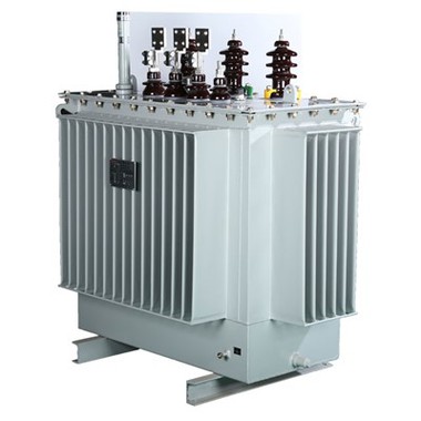
The oil immersed transformer is composed of a body, an oil tank, a cooling device, a protection device, and an outgoing device.
The body of an oil immersed transformer includes an iron core, winding (winding), insulation, leads, and tap changer; The fuel tank includes the fuel tank body and accessories (oil drain valve, grounding screw, trolley, nameplate, etc.); The cooling device includes a radiator and a cooler; The protective device includes an oil storage tank, an oil pointer, a safety airway, a moisture absorber, a temperature measuring element, and a gas relay; The outgoing device includes high and low voltage bushings.
1. Iron core: The iron core is one of the most basic components of a transformer, which is the magnetic circuit part of the transformer. The primary and secondary windings of the transformer are on the iron core. To improve the magnetic conductivity of the magnetic circuit and reduce eddy current losses in the iron core, the iron core is usually made of 0.35mm silicon steel sheet with surface insulation. The iron core is divided into two parts: an iron core column and an iron yoke. The iron core column is equipped with a winding, and the iron yoke connects the iron core to close the magnetic circuit.
2. Winding (coil): The winding is also one of the most basic components of a transformer. It is the circuit part of a transformer, usually wrapped in copper or aluminum wire wrapped in insulating paper. The winding connected to the high-voltage power grid is a high-voltage winding, and the winding connected to the low-voltage power grid is a low-voltage winding. The function of the winding is to carry current, generating magnetic flux and induced electromotive force.
3. Accessories: The accessories of the power transformer include oil tank, conservator, tap changer, safety airway, insulation sleeve, etc. Its function is to ensure the safe and reliable operation of the transformer.
① Oil tank: The oil tank is the outer shell of an oil immersed transformer, where the iron core and winding of the transformer are placed. The tank is filled with transformer oil for insulation, and there are other insulation methods besides oil insulation.
② Oil conservator (conservator): installed on the upper left side of the oil tank to isolate the inside of the tank from the outside.
③ Safety airway (explosion-proof tube): installed on the top cover of the fuel tank to protect the equipment and prevent damage to the fuel tank in the event of a malfunction. When a transformer malfunctions and generates a large amount of gas, the pressure inside the oil tank increases, and gas and oil will break through the explosion-proof film and spray outward to prevent the oil tank from bursting.
④ Gas relay (gas relay): installed in the pipeline between the oil tank and storage tank of the transformer, mainly as a protective device. There is a float with a mercury switch inside and a baffle that can drive the mercury switch. When the transformer malfunctions, the generated gas accumulates in the upper part of the gas relay, the oil level drops, the float sinks, and the mercury switch is connected to send a signal; When a serious fault occurs in the transformer, the oil flow breaks through the baffle, and the baffle deflects, driving a mechanism to connect another mercury switch, sending a signal and tripping.
⑤ Tap changer: In the power system, in order to control the output voltage of the transformer within the allowable range, the number of turns of the primary winding of the transformer needs to be adjusted within a certain range. Therefore, the primary winding is generally equipped with a tap, called a tap changer. By connecting switches with different connectors, the number of turns of the original winding can be changed to achieve voltage regulation. Tap changer is divided into on-load tap changer and off load tap changer.
⑥ Insulating sleeve: installed on the oil tank cover of the transformer, it is used to lead the coil lead end out of the oil tank and insulate the lead from the oil tank. Porcelain insulated sleeves are used for voltages below 1KV, gas-filled or oil-filled sleeves are used for voltages between 10-35KV, and capacitive sleeves are used for voltages above 110KV.
⑦ Transformer oil: Requirements: High medium strength and low viscosity, high ignition point and low solidification point, free from impurities such as acid, alkali, dust, and moisture. Function: Strengthen insulation and heat dissipation
PRODUCT LINK
http://www.switchgear-china.com/power-distribution-transformer/oil-immersed-transformer/high-voltage-oil-immersed-distribution.html
PRODUCT PHOTO


This product is usually customized.
We are a manufacturer and have a professional technical department that can design and provide solutions according to customer needs.
Please click on the button below to send us the information, and our sales personnel will contact you to provide you with the design drawings
Here are our customer examples for your reference
Vietnamese customers
Data Sheet N° 2-A: Transformer H61 33 kV/400V of 100 kVA
|
DESIGNATIONS |
S UNITS |
SPECIFIC DATA |
CANDIDATE DATA |
|
Maker |
|
To be indicated |
|
|
Reference standard |
|
IEC 60076 |
|
|
Type |
|
Phase |
|
|
Vat |
|
Hermetic |
|
|
Execution |
|
Tropicalized |
|
|
Dielectric |
|
PCB-free oil |
|
|
Installation |
|
On pole |
|
|
Operating ambient temperature |
°C |
45 |
|
|
Rated frequency |
Hz |
50 |
|
|
Rated power |
Kva |
100 |
|
|
Rated primary voltage |
Kv |
33 |
|
|
Isolation level assigned to primary school |
Kv |
36 |
|
|
Number of phases in primary school |
|
03 |
|
|
Secondary voltage |
V |
400/230 |
|
|
Voltage adjustment range on the M side when unladen |
% |
±2.5 |
|
|
Coupling |
|
Yzn11 |
|
|
Short circuit voltage |
% |
4 - 4.5 |
|
|
Neutral sized for one load |
% |
100 |
|
|
Maximum vacuum losses |
W |
230 – 460 |
|
|
Losses due to Maxi load |
W |
1450 - 2350 |
|
|
Maximum steady-state oil temperature |
°C |
55 |
|
|
Maximum temperature of the windings in steady state |
°C |
60 |
|
|
Winding material |
|
Electrolytic copper |
|
|
Maximum noise level |
Db |
52 |
|
|
50Hz industrial frequency hold, 1 min |
Kv |
50 - 70 |
|
|
Shock wave resistance (1.2/50 micros) |
Kv |
125 - 170 |
|
|
Cooling |
|
ONAN |
|
|
Nameplate |
|
01 |
|
|
Grounding connection |
|
01 |
|
|
Dimensions Height/width/depth |
mm x mm x mm |
1200 X 1050 X 710 |
|
|
Total mass of transformer including oil |
Kg |
400 |
|
|
Oil mass |
Kg |
90 |
|
|
PAINT |
|
||
|
|
|
Tropicalized and anti-rust |
|
|
|
|
Layers |
|
|
|
|
Binder |
|
|
|
|
Colour |
|
|
|
|
Plans and technical diagrams to be provided. |
|
IF NEED MORE DETAILES,PLEASE FEEL FREE YO CONTACT US