Common faults of high and low voltage switchgear
Jun 07, 2021
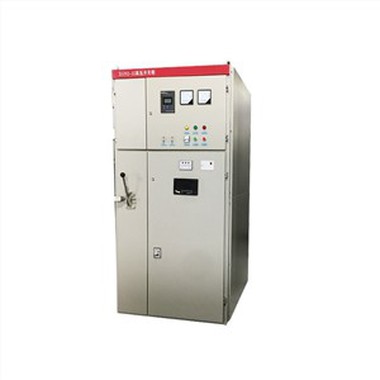
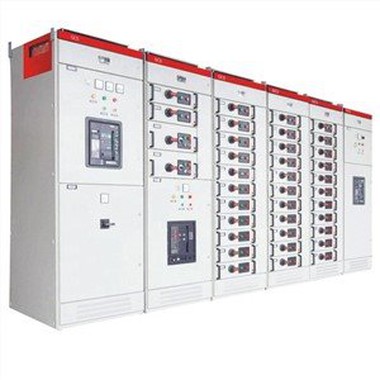
The high and low voltage switchgear is a kind of electrical equipment. The external line first enters the main control switch in the cabinet, and then enters the sub-control switch, and each branch is set according to its needs. Such as instrumentation, automatic control, motor magnetic switch, various AC contactors, etc. Some also have switch cabinets for high-voltage and low-voltage rooms, as well as high-voltage busbars, such as power plants. Machine failure will inevitably occur after the equipment is used for a long time. We will show you how to solve the problems when the high and low voltage switchgear fails.
Suddenly trip during operation
1. Failure phenomenon:
The cause of this failure is protection action. The high-voltage cabinet is equipped with over-current, quick-break and temperature protection. When the line or transformer fails, the protective relay operates to trip the circuit breaker. After the trip, the green switchgear opening indicator light is on, the high-voltage cabinet or the central signal system has an audible and visual alarm signal, and the integrated protection device has an alarm message for protection action.
2. Judgment method:
The cause of the fault can be judged according to the alarm information. In this high-voltage cabinet, there is no alarm indication for the transformer temperature protection action and the internal mechanical failure of the vacuum circuit breaker. The transformer temperature protection action needs to be queried on the transformer or on the background interface. The protection actions such as over-flow rate interruption can be clearly judged on the integrated protection device. .
3. Treatment method:
The overcurrent protection action causes the circuit breaker to trip because the line is overloaded. The user should be consulted with the user to reduce the load before the power is sent to prevent the trip again after the power is sent. When the quick-break protection trips, check the bus, transformer, and circuit. Find the short-circuit fault point and remove the fault before powering on. The transformer temperature protection action is because the transformer temperature exceeds the set value. If the setting is correct, you must try to reduce the temperature of the transformer. It can be ventilated to reduce the ambient temperature, and the load can also be reduced to reduce the temperature rise of the transformer. If the setting value of the temperature protection is too small, you can increase the setting value. Through the above methods, the temperature is lowered and the contact is opened, so that the circuit breaker can transmit power.
Energy storage failure
1. The failure of electric energy storage is caused by motor failure, control switch damage, improper adjustment of travel switch, and open circuit of other parts of the circuit. The manifestations include the motor does not rotate, the motor does not stop, and the energy storage is not in place.
2. Improper adjustment of the travel switch:
The limit switch is a limit switch that controls the energy storage position of the motor. When the motor is stored in place, cut off the power of the motor. If the limit is too high, the energy storage of the mechanism is full, and the motor will not stop when idling. Only cut off the power control switch to stop the motor. When the limit adjustment is too low, the motor will stop before the energy storage is full. The switch cannot be closed due to insufficient energy storage. The method of adjusting the limit is to manually store energy slowly to find the correct position, and tighten it.
3. Motor failure:
If the motor windings are burnt, there will be peculiar smell, smoke, and control switch tripping. If there is voltage across the motor, the motor will not rotate. It is judged that the motor is damaged, and the motor is replaced.
Closing failure
1. Closing faults can be divided into electrical faults and mechanical faults. There are two kinds of closing methods: manual and electric. The failure to close manually is generally a mechanical failure. The switch can be closed manually, but the switch cannot be closed by electric is an electrical fault. When the high-voltage switchgear cannot be closed electrically, there will be protection actions, protection failures, electrical interlocks, auxiliary switch failures, etc.
2. Protection action:
It has been analyzed before that the protection action causes the circuit breaker to trip. After the fault is removed, the comprehensive protection device is reset before power can be sent. In addition, for the load switch + fuse cabinet, if the fuse blows once, the load switch may not be closed.
3. Protection failure:
Now the high-voltage cabinet is equipped with five prevention functions. For the middle cabinet, it is required that the switch is not in the operating position or the test position and cannot be closed. That is, if the position switch is not closed, the motor cannot be closed. This kind of fault is often encountered during the closing process. At this time, the working position or test position light is off. Move the switch trolley slightly to close the limit switch to close.
4. Electrical interlock failure:
Electrical interlock failures are generally improper operation, which cannot meet the closing requirements. For example, although the incoming bus coupler is one opening and one closing, the handcart in the opening cabinet is pulled out, and the secondary plug is not plugged in. If the interlock circuit breaks down, use a multimeter to check the faulty part.
5. Disconnection fault of control circuit:
In the control loop, the control switch is damaged, the circuit is disconnected, etc., so that the closing coil cannot be energized. At this time, there is no sound of action of the closing coil. There is no voltage across the measuring coil.
6. Failure of closing coil:
The closing coil is burnt out, and there are peculiar smells, smoke, and control switch tripping. The closing coil is designed for short-time work, and the energizing time cannot be too long. After the closing failure, the reason should be checked in time, and the compound brake should not be reversed multiple times, because the coil is easily burned out due to the large current.
Failure of opening
Opening faults can also be divided into mechanical faults and electrical faults. Electrical faults mainly include control circuit open circuit, coil fault, auxiliary switch fault, etc.
1. Failure phenomenon:
Obvious phenomena such as smoke, peculiar smell, and control switch tripping occur when the opening coil burns out. The open circuit fault of the control circuit means that the transfer switch and other parts are disconnected, and the trip coil cannot be energized at this time.
2. Use a multimeter to measure the resistance at both ends of the coil when checking the coil failure.
PT cabinet voltage failure
1. PT cabinet voltage failure, the main reason may be PT cabinet voltage secondary circuit miniature circuit breaker tripping, PT cabinet voltage primary circuit fuse blown, PT cabinet secondary harmonic elimination device alarm, PT cabinet voltage lack phase, PT cabinet voltage mutual inductance Burned out.
2. The PT cabinet voltage and voltage secondary circuit miniature circuit breaker trips, which means that the voltage of the entire voltage circuit disappears, but the primary charged display still lights up. The miniature circuit breaker protects the voltage secondary circuit, and the voltage circuit cannot be short-circuited. If a short circuit occurs, the miniature circuit breaker trips to protect the voltage transformer and the secondary circuit. Secondly, when the entire system is fed into high voltage, the PT cabinet voltage secondary circuit miniature circuit breaker It often trips and can operate normally after re-closing the miniature circuit breaker. This is due to the inrush current generated by the transformer, excitation transformer, etc. and the components, and the PT cabinet voltage transformer has a small capacity. The miniature circuit breaker is a secondary circuit for protecting the voltage. The rated current is usually small, which is the influence of the entire system on the voltage secondary circuit.
3. The secondary resonance elimination device of the PT cabinet alarms. Since the voltage transformer is a weak link in the entire system, the quality of the power grid has a great impact on it. When the system voltage has resonance interference, the secondary resonance elimination device works to suppress part of the resonance interference And call the police. When the resonance interference exceeds the rated upper limit of the secondary resonance elimination device, the PT cabinet voltage primary circuit fuse will be blown to protect the voltage transformer. It is more likely that the PT cabinet voltage transformer may appear when the resonance interference is quite serious. In the case of burnout, these are the effects of grid resonance on the PT cabinet.
4. PT cabinet voltage transformer resonance elimination device is divided into primary resonance elimination and secondary resonance elimination. Generally, it is recommended not to install the primary resonance elimination and the second resonance elimination at the same time. In the neutral grounding system, it is recommended to use the second harmonic elimination.